POWER SUPPLY
8 – 32 VDC
INTERNAL BATTERY RECHARGE VOLTAGE
10 – 32 VDC, built-in 7.4 V, 1Ah lithium battery
BATTERY AUTONOMY
up to 5 hours
MAXIMUM CURRENT DRAW
1,2 A at 12 V
ENVIRONMENTAL
Operating temperature: 0 ÷ +45°C
Storage temperature: – 20 °C ÷ 60 °C
Operating relative humidity: 10 % ÷ 80 % without condensation
DIMENSIONS
155x178x55 mm (excluding Bluetooth antenna)
WEIGHT
1,2 kg
OSCILLOSCOPE:
CHANNELS
4 independent input channels with analogue bandwidth of 10 MHz (-3 dB); sampling rate 20MSamples/sec at 10 bit with 1 or 2 channels active, 10 MSamples/sec at 10 bit with 3 or 4 channels active
MAX INPUT VOLTAGE
+/- 50 Vmax, AC or DC couplingbr
VERTICAL SCALE FOR EACH CHANNEL
from 20 mV/Div to 50 V/Div
HORIZONTAL SCALE
from 500 ns/Div to 5s/Div
TRIGGER
source CH1, CH2, CH3, CH4, selectable, trigger delay
DISPLAY MODE
Normal, Auto, Single shot
MEASUREMENT OF FOLLOWING VALUES
frequency, period, RMS, Vmax, Vmin
MULTIMETER:
GALVANIC INSULATION
up to 1 kV for safe measurements
VOLTAGE MEASUREMENTS
Maximum measurable voltage: ± 400VDC, input impedance 4.7 MΩ, 3 digit resolution; three value ranges, with automatic or manual scale selection: 0-6 V, 6-60 V, 60-400 V AC/DC
RESISTANCE MEASUREMENTS
Three value ranges, with automatic or manual scale selection: 0-1000 Ω, 1-100 kΩ, 100 – 10 MΩ, resolution: 3 digits
CURRENT MEASUREMENTS
Current measurements performed by connecting TEXA “BICOR” series probes to the jacks on the front of the tool
TNET FUNCTION
Troubleshooting on CAN ISO11898, ISO11519 networks
BPP FUNCTION
Troubleshooting on starting systems Voltage measurements: DC up to 50VDC
ELECTROMAGNETIC COMPATIBILITY
ETSI EN 301 489-17 V 1.2.1 EN 6/326/1
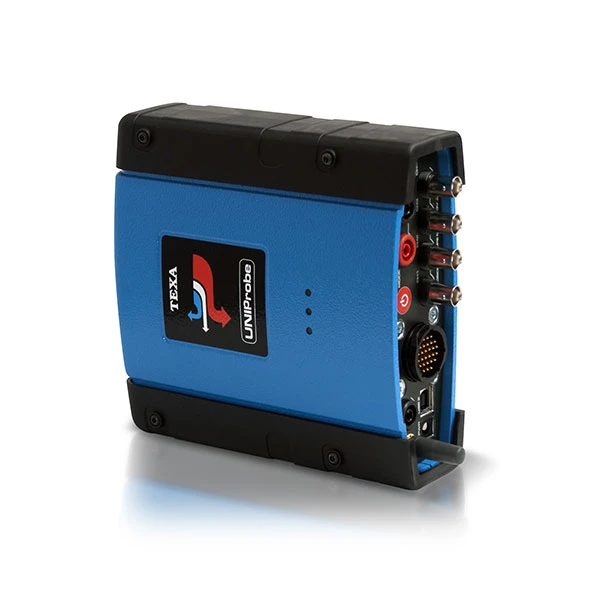
UNIProbe is the most complete and performing solutions comprising 6 different instruments inside the same device:
OSCILLOSCOPE
With four independent analogue channels, complete with SIV function for interpreting the measure signal (with IDC4 software).
BATTERY PROBE
For testing the battery, and analysing and checking the entire starting and charging system.

TNET
For electrical testing and analysis of automotive communication networks (CAN, VAN. LIN).
SIGNAL GENERATOR
To simulate the pulses generated by sensors and reproduce the commands generated by control units.

MULTIMETER
For voltage, resistance and current measurements.

PRESSURE TESTER
for checking fuel and turbocompressor pressure on all vehicles.
OPERATIVE SOFTWARE IDC5 AND MSS 
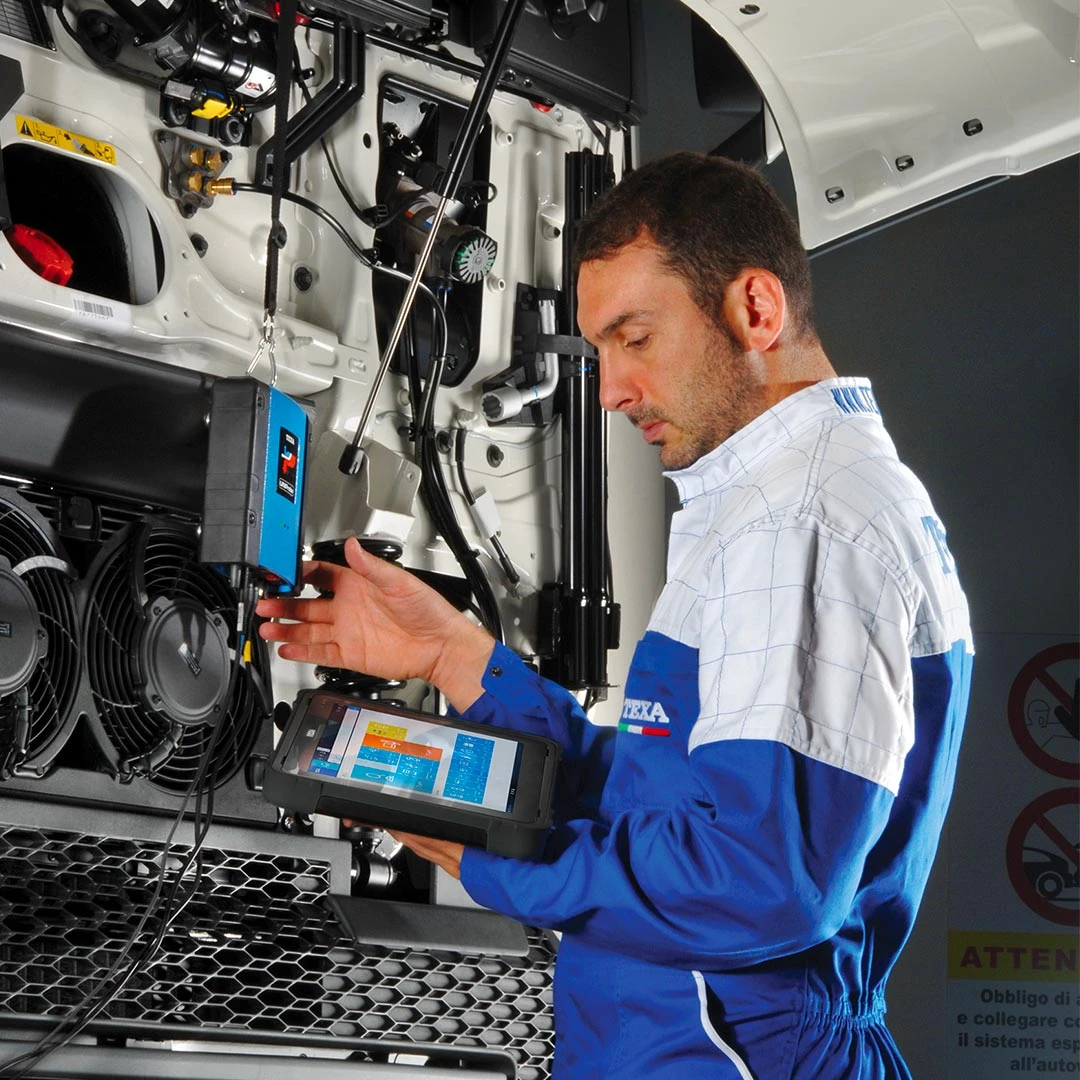
UNIProbe like all TEXA instruments, use the operative environment IDC5, the diagnosis and self-diagnosis software with built-in databank and exceptional coverage of makes and models. IDC5 is available both in a standard version for PC, MULTI PEGASO and AXONE 4, as well as in a POCKET version for portable viewing units of the AXONE line, but the software potential is the same in all. The wireless Bluetooth connection or connection via USB cable, allows for the transfer of data from the instrument to the viewing unit.
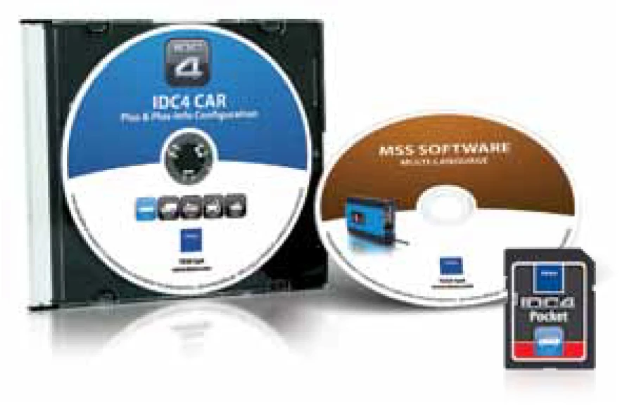 For those not having and not wishing to acquire the complete operative platform IDC5, MSS (Measurement System Software) is available, specific for UNIProbe, which enables only the functions of oscilloscope, battery probe, TNET, multimeter, pressure test and signal generator in manual mode.
SIV FUNCTION 
The oscilloscope test carried out with UNIProbe guarantees excellent detection of values and a precise identification of the measurement; but what the mechanic most needs is an efficient system to help him correctly identify the graphs processed by the instrument.
In order to declare if the signal analyzed is correct or not, it is, however, necessary to have reference data, values that clearly show which are the critical points to be analyzed.
This is why TEXA has developed a support that guides the mechanic throughout the test. The function developed is a software algorithm named S.I.V. (Signal Information Viewing).
Thanks to this system, UNIProbe do not simply view the signal; as they take the measurements and acquire the data, they process all information, analyze it and supply an assessment in real time.
They are, in fact, able to process the signals of the various sensors or actuators concerned by the measurement and compare the data acquired with that present in the internal database, thereby immediately showing any signal anomalies. This mode can be used simply and quickly, starting from the wiring diagram of the system to be analyzed or the list of components.
By selecting the device to be verified, we automatically activate the oscilloscope, which is already configured to correctly test the component.
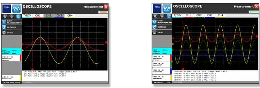
A PROFESSIONAL OSCILLOSCOPE
UNIProbe instrument offering exceptional performance and extremely high reliability levels. UNIProbe is able to detect 20 Msamples/sec with two channels active or 10 Msamples/sec with four channels active and a maximum incoming voltage of ± 50 Volts. This performance is distinctly higher than that offered by other solutions available on the market.
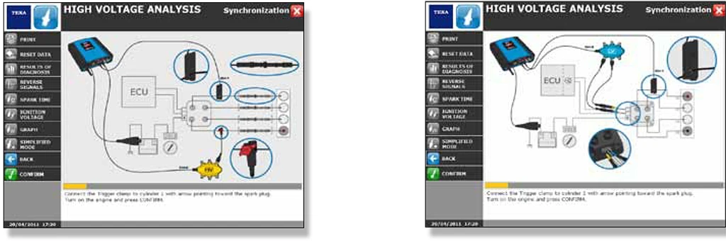
HIGH AND LOW VOLTAGE TESTS
UNIProbe, combined with specific cable kits, is able to measure and analyse both high and low voltage signals, with exceptional simplicity and efficiency. The test on the high voltage line (namely that which connects all electronic components operating with voltages of thousands of volts) allows, for example, for the testing of petrol engine ignition systems, monitoring the electrical impulses that reach the coils or spark plugs. With regards to hybrid engines that have been on the market for years, they are also fitted with 200 Volt power modules.
The measurements taken with an oscilloscope, even the most precise, in any case translates into a graph that the mechanic must be able to analyse. This is why UNIProbe has been developed as a support tool in interpreting data, thanks to specific software.
For low voltage tests, for example, acquiring the signal of a butterfly potentiometer, the software shows the typical bell curve of the acceleration and, if micro-interruptions are present, blocks the image, showing the presence of the anomaly on the graph.
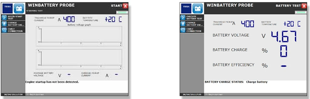
BATTERY, IGNITION AND RECHARGE TEST
With the Battery Probe function and the BPP kit, UNIProbe is able to quickly and easily carry out a complete test of the elements and components of the system comprising the starter motor, alternator and battery, thereby reaching a certain diagnosis and reliable repair. The BPP kit is equipped with four analogue inputs and two connectors for connection with the current clamp. A semi-automatic diagnosis system analyses the ignition system as a whole (therefore the individual components and wiring) in order to verify the origin of the fault. On the basis of the measurements obtained, the software therefore provides a possible diagnosis, indicating the most likely cause of malfunction. This translates into a report that can be printed and delivered to the customer and which provides details of the measurements and checks performed.
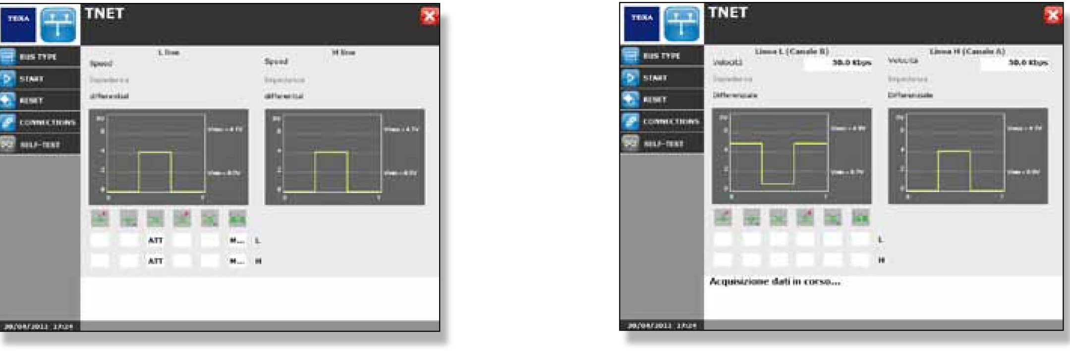
ELECTRICAL FUNCTION TEST OF NETWORKS
In the network communication BUS (e.g. CAN, VAN, LIN), electrical and electronic anomalies may not depend on the systems and components, but rather be the consequence of physical damages to the electronic network. This may occur, for example, following damage or physical deterioration of wiring. In other cases, on the other hand, it may depend on accidental interruptions of a wire during repair or assistance. It may, finally, derive from auxiliary ECUs and devices that have not been correctly installed. In all cases, thanks to UNIProbe with the integrated TNET module, the electrical analysis can be carried out directly on the wiring of various network types, with the test probes.
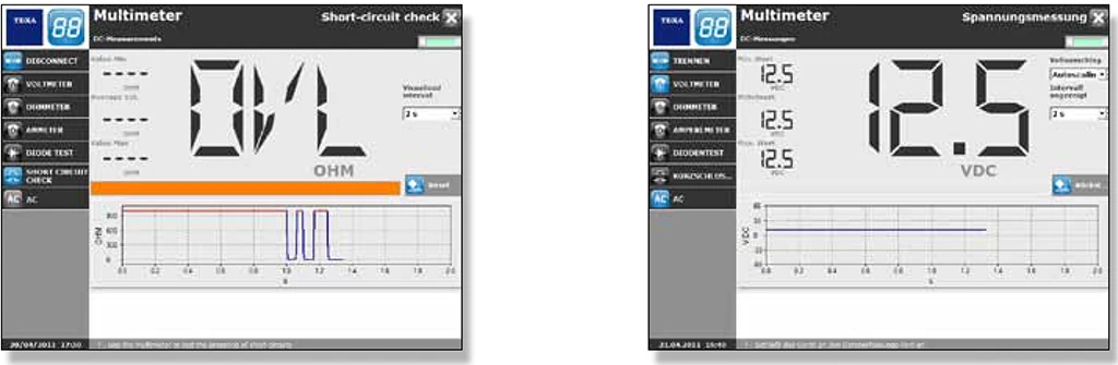
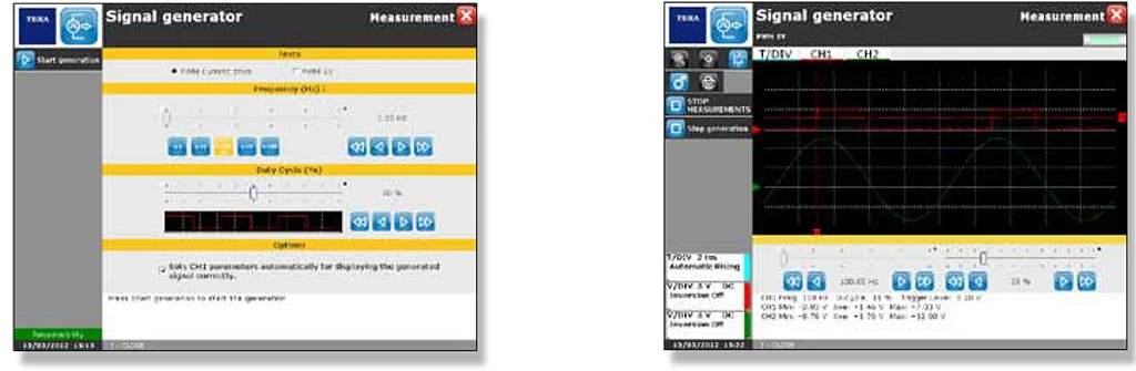
MULTI-METER FUNCTION
UNIProbe allows voltage, current and resistance to be measured with the utmost easiness; it also allows diode (to determine whether or not a diode is correctly functioning and how it is being polarised), continuity tests (to determine the presence of short circuit between two terminals) and data logger (to monitor slow signals such as voltage or variable resistances and record changes over time. As for TwinProbe, it is possible to measure current through a BICOR clamp.
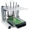
SIGNAL GENERATOR
UNIProbe are able to operate as a PWM signal generator for device testing. Tests can be carried out on mechanical components such as actuators, pressure switches of diesel engines, turbine blades or the EGR valve. Thanks to UNIProbe and TwinProbe, it can be assessed whether the anomaly depends on an electronic malfunction or a mechanical breakage. By using UNIProbe and TwinProbe in combination with the software IDC4, adjustments can be made and the effects observed by comparing them with the parameters proposed by the self-diagnosis.


-150x150w.webp)


-120x100w.webp "LAUNCH")


